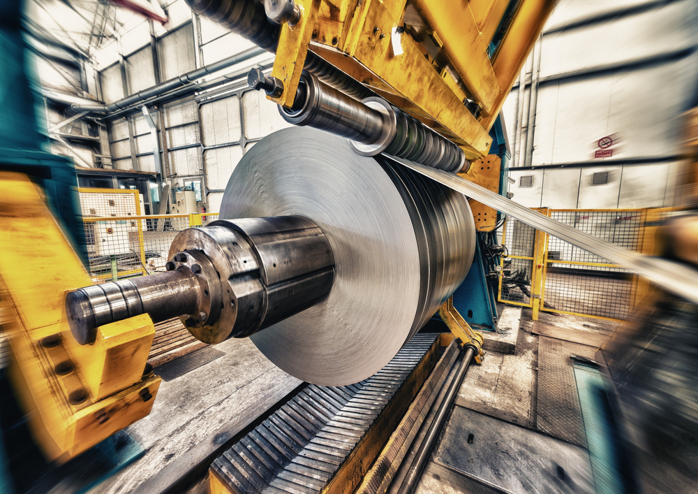
Anodising is a process that strengthens aluminium and protects it from corrosion. It also improves durability and lets you add decorative finishes.
Unlike coatings or paints, anodising doesn’t add material on top. Instead, it changes the surface structure, making the aluminium harder and more resilient. When combined with the advantages of aluminium, such as lightweight strength, recyclability, and corrosion resistance, anodising creates an exceptionally durable and sustainable material for fabrication.This makes anodised aluminium one of the most versatile materials used in modern fabrication.
Understanding the Aluminium Anodising Process
The aluminium anodising process involves carefully controlled stages that convert the metal’s surface into an oxide layer. Here’s how it works:
Cleaning and Preparation – The aluminium is cleaned to remove impurities or grease.
Anodising (Electrochemical Treatment) – The aluminium is placed in an acid electrolyte bath and an electric current is passed through it. This causes oxygen ions to bond with aluminium atoms, forming an oxide layer.
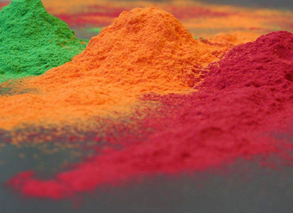
Colouring (Optional) – The porous surface can be dyed to achieve a wide range of colours and finishes.
Sealing – The surface is sealed to close the pores and lock in colour, increasing corrosion resistance and durability.
This aluminium anodising process ensures a long-lasting, uniform finish ideal for both functional and decorative applications.
Key Anodising Benefits
There are many anodising benefits that make it a preferred choice for engineers, designers, and fabricators alike:
Superior Corrosion Resistance
Anodised aluminium is highly resistant to corrosion. The oxide layer shields it from moisture and salt, making it ideal for outdoor and marine applications.
Enhanced Durability
Anodised surfaces are much harder than untreated aluminium. This added wear resistance makes it perfect for parts exposed to friction, handling, or harsh operating environments. Among all available metal finishes, anodising offers a good balance of aesthetics, protection, and durability, all in a single process.
Improved Aesthetic Appeal
Anodising allows aluminium to retain its metallic appearance while adding colour and sheen. From subtle matte finishes to bold hues, anodised aluminium provides both function and style.
Low Maintenance
Because the oxide layer is integral to the metal (not a coating), it won’t peel or flake. Cleaning is simple, usually requiring just mild soap and water, making anodised aluminium a cost-effective long-term choice.
Environmentally Friendly Process
The aluminium anodising process uses non-toxic materials, produces minimal waste, and enhances recyclability, aligning perfectly with sustainable manufacturing goals.
Applications of Anodised Aluminium
The uses of aluminium are incredibly diverse, ranging from everyday consumer goods to complex industrial structures. Anodised aluminium is especially valued across these applications for its enhanced performance, durability, and appearance. Common applications include:
Architectural structures – windows, curtain walls, and façade panels
Automotive and transport – trims, body parts, and protective components
Consumer products – electronics, kitchenware, and lighting
Industrial fabrication – machinery, frameworks, and enclosures
At Salamander Fabrications, we utilise anodising to ensure every aluminium component meets exacting standards of performance and design.
Why Choose Salamander Fabrications for Anodised Aluminium?
With decades of expertise in metal fabrication and finishing, Salamander Fabrications delivers precision-engineered aluminium products that stand the test of time. Whether you require anodised aluminium for structural use or decorative purposes, our team ensures the right finish for your project’s needs.
We combine craftsmanship with innovation, offering custom fabrication and finishing services that help your products perform better and look exceptional.
Frequently Asked Questions
What is anodised aluminium used for?
It’s used in applications that require corrosion resistance, visual appeal, and durability from architectural features to industrial components.
Is anodised aluminium rust-proof?
Yes. The anodising process prevents oxidation and corrosion, ensuring aluminium remains rust-free even in challenging environments.
Can anodised aluminium be coloured?
Absolutely. During anodising, the porous surface can absorb dyes, allowing for a wide range of colour finishes before sealing.
How long does anodised aluminium last?
Anodised aluminium can last for decades if looked after. Its oxide layer is part of the metal itself, so it keeps the surface protected from wear and corrosion.
Is anodising environmentally friendly?
Yes. The aluminium anodising process is safe, non-toxic, and produces minimal waste, making it a sustainable finishing option.
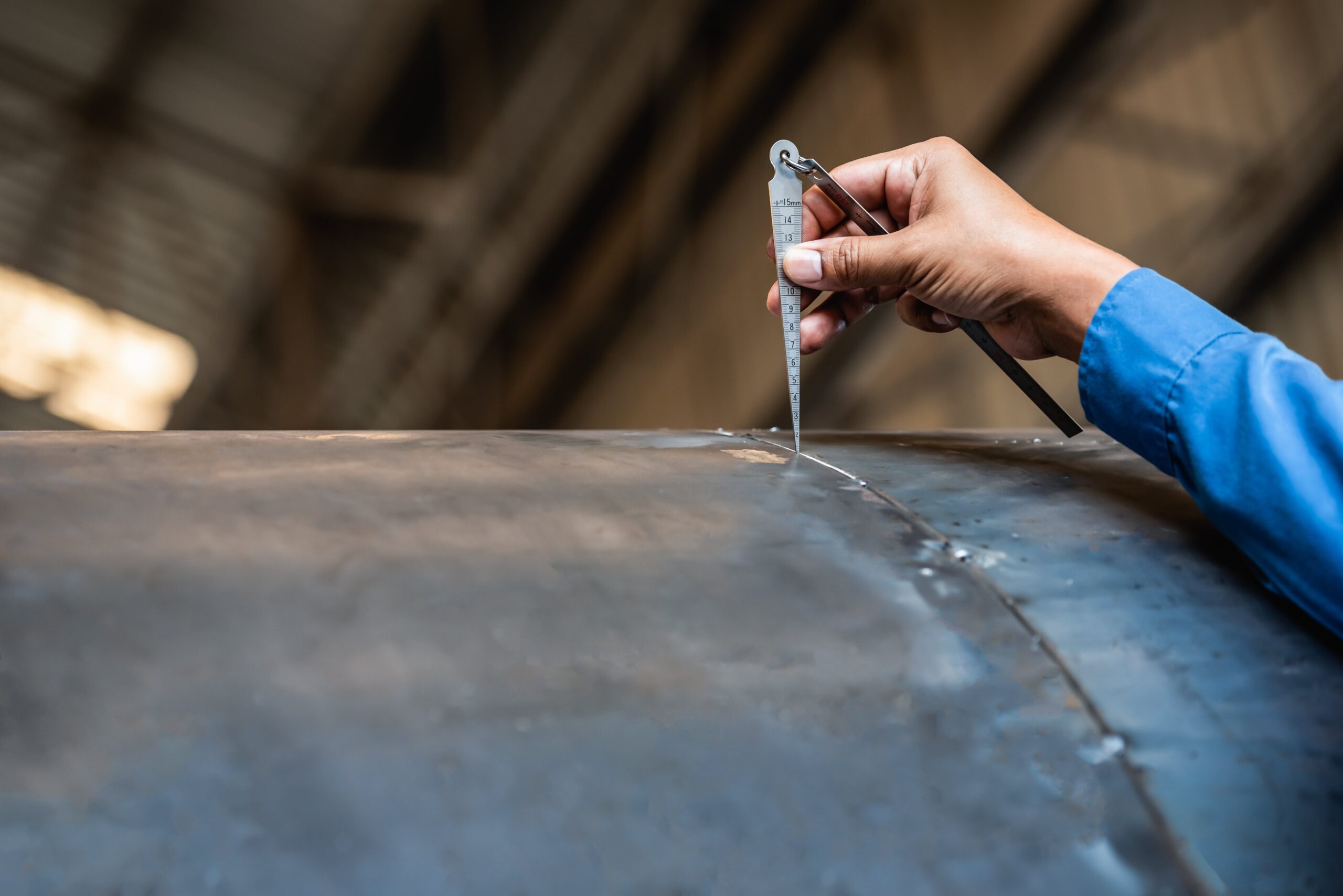
Heat treatment of metals helps to achieve the correct strength, durability and performance. Not only does it improve the mechanical properties of metal but it helps to prevent welding defects and structural issues.
At Salamander Fabrications, we understand the science and precision behind metal treatment processes, ensuring every component performs at its best, even under extreme conditions.
What Is Heat Treatment of Metals?
Heat treatment of metals involves heating and cooling metal materials under controlled conditions to alter their physical and mechanical properties without changing their shape. The goal is to enhance characteristics like hardness, ductility, and tensile strength depending on the intended use.
These treatments help metals stand up to stress, wear, and temperature changes, which are essential in industries from construction to automotive engineering.
Key Heat Treatment Processes
There are several types of heat treatment methods, each designed for specific results. The most common include annealing, quenching, and tempering.
Annealing
Annealing is a heat treatment process that softens metal, making it more ductile and easier to work with. During annealing, the metal is heated to a specific temperature and then slowly cooled. This reduces hardness, relieves internal stresses, and improves machinability.
Typical applications include sheet metal fabrication, wire production, and components requiring precise bending or forming.
Quenching
Quenching involves heating the metal to a high temperature and then rapidly cooling it, often in water, oil, or air. This process increases hardness and strength by locking the metal’s microstructure into a tough, stable form.
Quenching is widely used in tools, gears, and high-stress mechanical parts where superior strength and wear resistance are essential. However, the rapid cooling can also make the metal brittle, which is why quenching is often followed by tempering.
Tempering
Tempering is a follow-up process to quenching. After a metal has been hardened, it is reheated to a lower temperature and then cooled again. This reduces brittleness while maintaining strength, striking the ideal balance between toughness and hardness.
Tempering is especially important for components exposed to repeated stress or impact, such as springs, blades, and structural supports where the strongest metal is necessary.
Applications of Heat Treatment in Fabrication
At Salamander Fabrications, heat treatment processes are integral to delivering high-quality metal components for a wide range of industries. Common applications include:
Structural steelwork – improving durability and stability in large-scale frameworks.
Precision components – ensuring exact tolerances and enhanced performance.
Custom fabrication – tailoring metal properties to suit unique client specifications.
By combining advanced fabrication techniques with expert heat treatment processes, we help clients achieve consistent results that meet the toughest engineering standards.
Why Choose Salamander Fabrications?
With decades of experience in metal fabrication and finishing, Salamander Fabrications is trusted by leading businesses across the UK for reliable, high-quality metalwork solutions. Our commitment to precision, performance, and customer satisfaction ensures every project is completed to the highest standard.
Whether you need annealing, quenching, or tempering as part of your fabrication process, our team can advise on the right approach for your materials and applications.
Get in Touch
If you’re looking for expert support in heat treatment of metals or bespoke fabrication services, contact Salamander Fabrications today. Talk to our team today, and we’ll help you choose the right process and finish for your project.
FAQs
What is the purpose of heat treatment of metals?
The main purpose of heat treatment is to improve a metal’s mechanical and physical properties. Depending on the process used, it can increase strength, hardness, and wear resistance, or make the material softer and easier to machine.
Why is heat treatment important in fabrication?
In metal fabrication, heat treatment ensures that components have the right balance of hardness, strength, and ductility for their intended use. It also helps minimise welding defects by relieving internal stresses that can lead to cracking or distortion during welding.
What metals can be heat treated?
Many metals can undergo heat treatment, including carbon steel, stainless steel, aluminium alloys, copper alloys, and titanium. The exact process and temperature range depend on the metal’s composition and desired outcome.
What’s the difference between annealing and tempering?
Annealing softens metal and improves its ductility by allowing its structure to reform slowly. Tempering, on the other hand, is used after hardening (quenching) to reduce brittleness while maintaining strength.
Galvanised steel is one of the most widely used materials in modern manufacturing due to its durability, cost effectiveness and the zinc coating that prevents rust.
What is Galvanised Steel?
Galvanised steel is steel that has been coated in a thin layer of zinc to protect it from rust and corrosion. The zinc coating acts as a barrier to the environment so increases the metal’s durability and strength compared to metals that rust. This, alongside the versatility, makes it popular for a variety of projects and industries.
How is it different from other types of steel?
Galvanised steel is specifically designed to combat rust. When thinking about mild steel vs stainless steel, there are a few key differences. Mild steel is prone to corrosion when exposed to moisture unless it is painted or treated. Stainless steel naturally resists corrosion as it contains chromium, however this does make it more expensive. Ideal for outdoor use and a cost-effective alternative, galvanised steel is a great option for outdoor use.
Key Benefits of Galvanised Steel
Galvanised steel benefits include exceptional durability, corrosion resistance, and long-term cost savings. They are widely recognised across many industries.
Corrosion Resistance
The addition of a protective zinc coating makes galvanised steel highly resistant to corrosion, even in harsh and challenging environments. The zinc layer acts as a physical barrier and also offers sacrificial protection, meaning it corrodes in place of the steel underneath. This protection extends into hard-to-reach areas such as sharp corners, edges, and recessed surfaces that other coatings may not adequately cover, ensuring uniform corrosion resistance throughout the entire component.
Durability
Galvanised steel is known for its long-lasting performance. In average conditions, a zinc-coated steel product can last more than 50 years without significant breakdown. Even in more aggressive environments with high moisture or water exposure, such as coastal or industrial areas, it can provide effective protection for over 20 years without requiring maintenance. This longevity makes it a reliable choice for infrastructure, construction, and outdoor applications.
Cost-effective
Although the initial cost of galvanising may be higher than some other protective methods, its long service life and lack of maintenance needs result in significant savings over time. By reducing the need for repairs, replacements, or touch-ups, galvanised steel proves to be a cost-effective solution for both short-term projects and long-term investments.
Ready to Use
Galvanised steel arrives from the supplier fully coated and protected, requiring no further surface treatment, painting, or preparation before installation. This reduces lead times and labour costs on-site, making it ideal for projects with tight schedules or limited resources. Its ready-to-use nature simplifies logistics and speeds up construction timelines.
Environmentally Friendly
Galvanised steel is a sustainable material choice. The galvanising process does not produce significant waste. At the end of its life, galvanised steel can be recovered and reused without loss of quality, contributing to circular economy practices and reducing the environmental footprint of construction and manufacturing projects.
How is Galvanised Steel Made?
There are a few methods of galvanisation:
1. Hot Dip Galvanising
The steel is dipped into zinc that is around 460 degrees which forms a metallurgical bond that results in a firm layer of pure zinc. Once the metal is pulled out of the molten zinc, the pure zinc mixes with the oxygen in the atmosphere to form zinc oxide. The zinc oxide then reacts with the carbon dioxide and forms zinc carbonate which completes the final protective coating. This is a cost-effective method that can be quickly done and on complex shapes too.
2. Pre-galvanising
This method is performed at the very first stage of production. It involves rolling sheet metal through a cleaning agent to prime the material for galvanising. The metal is then passed through molten zinc and immediately recoiled. The benefit of this method is that coils of steel can be quickly galvanised on a larger scale with a more unified coating as opposed to the hot-dip method.
3. Electrogalvanising
This method doesn’t involve any molten zinc. Instead, an electric current is used to reduce positively charged zinc ions to zinc metal which is then deposited on the positively charged steel. The main benefit of this technique is that it creates an even coating on the steel. However, the coating is thinner than when the hot dip method is used and has a shorter lifespan.
Common Uses of Galvanised Steel
Galvanised steel uses are found in a wide range of industries. Wherever there is a risk of corrosion, galvanised steel should be used.
Construction – Galvanised steel is widely used in the construction industry and commonly found in beams, columns, and frameworks, where long-term reliability is essential. Its ability to withstand exposure to the elements with minimal maintenance makes it a preferred choice for both residential and commercial buildings, as well as infrastructure projects like bridges and walkways.
Automotive – Galvanised steel is often used in the manufacturing of cars, trucks, and other vehicles for body panels, chassis parts, and undercarriage components to provide resistance against rust and extend vehicle life. The combination of strength and corrosion protection helps improve safety, reduce repair costs, and maintain vehicle appearance over time.
Agriculture – This material is a staple in agricultural applications due to its ability to endure rough conditions, including exposure to moisture, chemicals, and outdoor weather. It is used in the construction of farm equipment, machinery frames, irrigation systems, fencing, livestock enclosures, feeders, and grain silos. Its long-lasting nature reduces the need for constant replacements, making it a practical and economical solution for farmers.
Marine – The marine industry requires materials that can perform reliably in wet, salty, and corrosive environments, and galvanised steel is well-suited for this role. It is used in boat trailers, docks, offshore platforms, ladders, and other structural or support components exposed to seawater or humid coastal air. The zinc coating offers a strong defence against saltwater corrosion, which significantly prolongs the service life of components in marine and coastal applications.
Industrial Fabrication – from appliances and electronics to machinery and equipment, galvanised steel is used in many manufacturing processes. This includes appliances, electrical enclosures and heavy machinery. Its ease of fabrication, combined with corrosion resistance and mechanical strength, makes it a versatile and dependable material in industrial design, assembly, and production processes.
Services at Salamander Fabrications
At Salamander, we’ve been working with all kinds of sheet metal fabrication technologies since 1968. We offer services such as, welding and laser cutting to companies all over the UK, and work with a huge range of sectors to provide them with quality products, quickly, efficiently and with excellent customer service every step of the way.
Metals are at the core of everything Salamander Fabrications does. From structural frameworks to custom enclosures and components, metals provide strength, form, and function. In the world of fabrication, it’s essential to understand different types of metal, that’s where ferrous vs non‑ferrous metals comes in. It’s important to know which type to use, when, and why can mean the difference between longevity under harsh conditions or frequent replacements.
What Are Ferrous Metals?
Ferrous metals primarily contain iron as their main component. This iron content gives these metals unique properties that make them a staple in many fabrication and manufacturing processes but does make them prone to rust. Characteristics include magnetism, strength and durability.
What Are Non-Ferrous Metals?
Non-ferrous metals are metals that do not contain iron. They are lightweight, highly resistant to rust and corrosion, and non-magnetic. These qualities make them ideal for projects exposed to harsh environments or where reducing weight is a priority.
Key Differences Between Ferrous and Non-Ferrous Metals
Iron Content
Ferrous and non-ferrous metals differ in several important ways, starting with their iron content. Ferrous metals contain iron, which gives them strength and durability but also makes them prone to rust and corrosion if not properly protected.
In contrast, non-ferrous metals do not contain iron, making them naturally resistant to corrosion and ideal for use in environments where exposure to moisture or chemicals is a concern.
Weight
Ferrous metals tend to be heavier due to their iron content, which makes them well-suited for applications where strength and load-bearing capacity are priorities.
Non-ferrous metals, such as aluminium and copper, are generally much lighter, offering advantages where reducing weight is critical, such as in aerospace or transportation.
Magnetic
Magnetic properties also set these metals apart. Ferrous metals are typically magnetic metals because of their iron base, whereas non-ferrous metals are non-magnetic, which can be beneficial in electronic and electrical applications where magnetism could interfere with performance.
Cost
Ferrous metals are often more affordable, primarily due to their abundance and established production processes.
Non-ferrous metals tend to be more expensive but offer benefits like enhanced corrosion resistance and lighter weight that can justify the higher price depending on the application.
Environmentally-friendly
Both ferrous and non-ferrous metals have strong recycling potential, but their recycling processes differ. Ferrous metals are widely recycled and easily separated using magnets, while non-ferrous metals require more specialised recycling methods. Nevertheless, both contribute significantly to sustainable manufacturing practices.
Examples of Ferrous and Non-Ferrous Metals
At Salamander Fabrications, choosing the right material is essential for delivering precision-engineered sheet metal products across industries. Here are some ferrous and non-ferrous metal examples:
Which metals are ferrous?
Typical uses for ferrous metals range from construction frameworks and automotive parts to industrial tools and heavy machinery, where durability and strength are critical.
Carbon steel
This has a higher carbon content than other types of steel making it extremely high in strength. It is commonly used in the manufacture of machine tools, gears, drills, blades and springs.
Alloy steel
This incorporates elements like chromium, nickel and titanium to provide greater strength and durability without increasing the weight. Alloy steel is often used in structural components, construction and automotive parts.
Stainless steel
Stainless stell is an alloy steel that contains chromium, which gives it excellent corrosion resistance and a sleek, clean finish. It is widely used in the production of kitchen equipment, medical instruments, architectural features, and components that require both durability and resistance to rust.
Cast iron
This contains iron, carbon and silicon. It is brittle, hard and resistant to wear which makes it ideal for water pipes, automobile engines, heavy machinery and stoves.
Wrought iron
This has such little carbon content that it is almost pure iron. It has great resistance to corrosion and oxidation. It is traditionally used for fencing and decorative ironwork.
Which metals are non-ferrous?
Non-ferrous metals are commonly used in electrical components, plumbing systems, roofing materials, aerospace parts, and many precision fabrication projects where performance and longevity are crucial.
Aluminium
Due to this metal being lightweight, soft and low strength, it can be easily cast, forged and welded but not suitable for high-temperature environments. It is a good choice for aircraft and automotive components as well as food packaging.
Copper
Highly ductile, malleable and thermal conductivity means that copper is primarily used in the electrical industry as wiring. It is also used for roofing, coins and mixed with zinc to make brass.
Zinc
This is a medium to low-strength metal with a low melting point and resistance to corrosion. Zinc is most commonly used in galvanising, the process of applying a zinc coating to steel to prevent rust. It can also be used in batteries and die casting.
Lead
This is a soft, dense, malleable metal which can withstand corrosion from moisture and acid. Due to this, it is widely used in electrical power cables, batteries and radiation shielding.
Nickel
Used in stainless steel production, batteries and electroplating, nickel is corrosion-resistant, tough and heat resistant.
FAQs
Which type of metal is best for outdoor use?
Non-ferrous metals are generally better suited for outdoor use because they are naturally resistant to corrosion and rust. Metals like aluminium, copper, and zinc are commonly used in roofing, cladding, and outdoor fixtures due to their ability to withstand moisture and environmental exposure. Stainless steel, while technically a ferrous metal, is also an excellent choice for outdoor applications thanks to its chromium content, which provides strong corrosion resistance.
Are non-ferrous metals better for electrical applications?
Yes, non-ferrous metals are typically better for electrical applications, especially copper and aluminium. Copper is the industry standard for wiring due to its exceptional conductivity, while aluminium is used where lighter weight is needed, such as in overhead power lines. These metals are also non-magnetic, which helps prevent electromagnetic interference in sensitive electronic equipment.
How can you tell if a metal is ferrous or non-ferrous?
One simple way to tell is by checking if the metal is magnetic. Ferrous metals (which contain iron) are usually magnetic, while non-ferrous metals are not. Another clue is whether the metal rusts. Ferrous metals are more prone to rust unless specially treated, whereas non-ferrous metals are naturally more corrosion-resistant. For a definitive answer, a material test or a spark test can be used in a workshop setting.
Can ferrous and non-ferrous metals be welded together?
Welding ferrous and non-ferrous metals together is possible, but it requires special techniques and filler materials. The differences in melting points, thermal conductivity, and chemical properties can cause issues like cracking, weak joints, or metal incompatibility. In many cases, alternative joining methods like brazing, soldering, or mechanical fastening are preferred over traditional welding.
From the foil in your kitchen drawer to the wings of an aircraft, aluminium is one of the most widely used and versatile materials in the modern world. For this reason, it is also a staple material in the world of sheet metal fabrication. But what is aluminium exactly? What makes this lightweight material so strong, corrosion-resistant and yet so easy to shape? This magical material has a unique combination of properties that make it indispensable across countless industries, and we’re here to tell you how and why!
In this guide, we’ll explore “what is aluminium?”, where it comes from, its key characteristics, and why it’s such an important part of everyday life.
Aluminium: Definition and basic facts
Aluminium is a lightweight metal typically found in the Earth’s crust. In fact, it’s the most abundant metal on our planet, making up about 8% of the crust’s mass. Physically, aluminium is soft, non-magnetic, and highly malleable. This means it can be shaped into thin sheets or made into wires with ease. It has a relatively low density, a melting point of 660°C, and it conducts heat and electricity rather well.
Its combination of lightness, strength and resistance to corrosion has made it a go-to material for applications where performance and durability matter.
How aluminium is produced
You won’t find aluminium in pure form in nature. Most of today’s aluminium is extracted from bauxite ore, which contains aluminium oxide (alumina) mixed with other minerals.
The production process has two main stages:
Refining (Bayer process): The bauxite is crushed, washed and treated with caustic soda at high temperature and pressure to dissolve the alumina. Impurities are filtered out before the alumina is precipitated, washed and dried into a fine white powder.
Smelting (Hall–Héroult process): The alumina is dissipated in molten cryolite and exposed to electrolysis, which separates the pure aluminium metal from oxygen.
Producing aluminium is energy intensive, which is why the industry is increasingly turning to renewable energy sources to reduce its carbon footprint. A key advantage is that aluminium is infinitely recyclable without losing quality. Recycling uses about 95% less energy than producing new aluminium, making it both an economic and environmental win.
Standout properties of aluminium
Now we’ve covered what is aluminium let’s look at some of its major benefits.
Lightweight: With a density of just 2.7 g/cm³, aluminium is about one-third the weight of steel.
Corrosion resistant: When exposed to air, aluminium forms a thin oxide layer that prevents further oxidation, making it naturally resistant to rust.
Strong yet flexible: It has a high strength to weight ratio but can be alloyed with other metals for added hardness and durability.
Highly malleable and ductile: It can be rolled into thin sheets, drawn into wires, or extruded into complex shapes.
Excellent conductor: Aluminium efficiently conducts heat and electricity, making it useful for wiring, electronics and cookware.
Non-toxic and safe: Widely used in food and beverage packaging without health risks.
100% recyclable: Can be reused endlessly without degrading in quality.
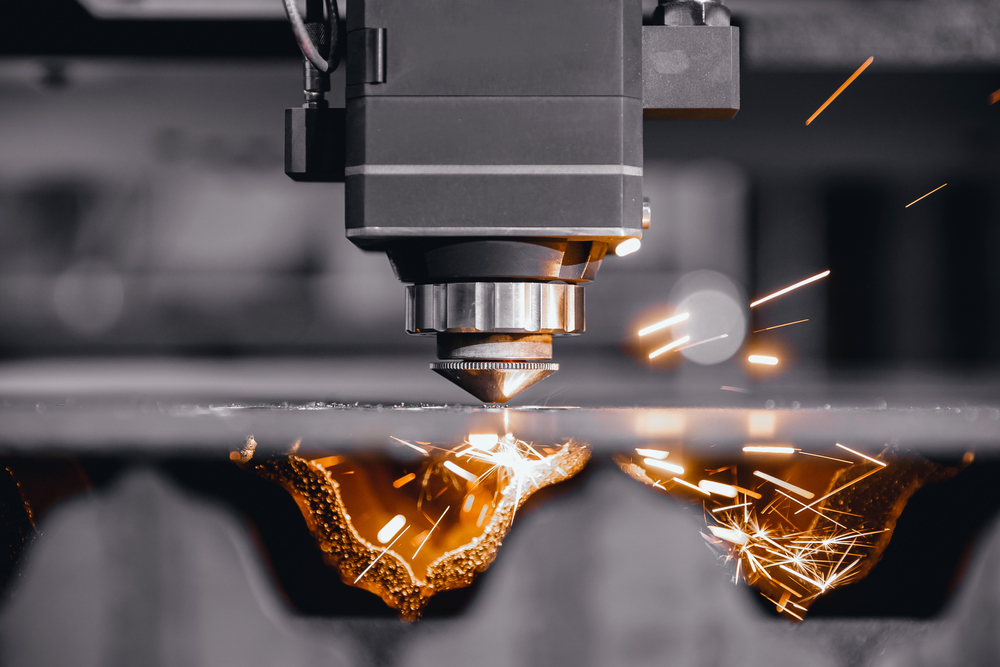
There are several ways you can form, shape and manipulate aluminium into the desired product you require. Knowing how to cut aluminium can be as easy as using a hand tool (like a hacksaw or utility knife for small scale projects) or more advanced power tools (such as circular saws or band saws). Here at Salamander Fabrications we make use of laser cutting technology, which offers the type of precision and control that you simply cannot replicate with manual or standard power tools. Other techniques also include plasma cutting and waterjet cutting.
There’s also more to working with aluminium than just cutting! Welding services are at the heart of most aluminium fabrication projects, primarily when it comes to joining parts together. Sheet metal folding is vital for producing parts with bends or angles, while powder coating services ensure the final product is durable and nice on the eye too!
Key applications and uses of aluminium
Aluminium’s versatility means it plays a role in almost every aspect of modern life. Some of its most common applications include:
Transport: Lightweight, helps improve fuel efficiency and reduce emissions in the transportation industry. Aerospace in particular relies heavily on aluminium for its strength-to-weight advantage.
Construction: From window frames and curtain walls to roofing and cladding, aluminium’s weather resistance and low maintenance needs make it ideal for construction projects.
Packaging: Aluminium cans, foil and food trays protect contents from light, moisture and air. This keeps products fresher for longer. Its recyclability also supports sustainable packaging goals.
Consumer goods: You’ll find aluminium in laptops, smartphones, sports equipment, and home appliances.
Energy sector: Aluminium is used in power lines, solar panel frames and other renewable energy infrastructure because it’s lightweight and conductive.
Contact Salamander Fabrications with your aluminium requirements
Aluminium is far more than just a common metal. It’s a cornerstone of modern industry and everyday life. Light, strong and endlessly recyclable, it’s a material that has shaped everything from architecture to transportation, technology, and packaging. As industries continue to innovate and sustainability becomes ever more important, aluminium’s unique properties ensure it will remain a key player in building a lighter, greener future.
We hope we have helped to answer the question – what is aluminium? If you have a project in design that involves aluminium and would like some advice or assistance in creating your product, please do not hesitate to contact us. Give us a call on 01484 843599, or send an email to sales@salamanderfabs.com.If you enjoyed reading this blog, you may like to take a read of our other post – Mechanical Properties of Materials Explained.
Forging is one of the oldest manufacturing processes for shaping metal. As there’s a range of techniques out there to treat metal, you may be confused as to what forging actually is. We’re here to help! In this blog, we go through all the ins and outs of forging, including the forging meaning, its types, the process, and its advantages.
At Salamander Fabrications, we have a range of high-quality sheet metal fabrication services. With years of experience, we offer end-to-end, full service projects so our expert team takes care of every single stage.
If you want to know more about the services we offer, feel free to get in touch with our sales team today at 01484 843599. We’d love to hear from you!
The Definition of Forging
Forging is essentially the use of compressive forces to shape metal- most of the time, the metal is heated (but not always!) and shaped using a hammer or die. The fact it’s still used today despite being one of the oldest metal shaping techniques shows its effectiveness as a process.
Once the metal reaches the ideal temperature, great pressure is used to shape the metal into the desired shape. This then creates some very strong manufactured metals, and the process can be used on all kinds of metals. The reason for forging’s strengthening ability is because it alters a metal’s grain structure and refines it by breaking down any impurities.
Basic and necessary forging equipment includes:
Forge: A forge is the heating equipment that helps the metal reach the required temperature.
Hammer: Hammers are used for harsh, high-impact force to strike and shape the metal.
Pressers: Creates a controlled force instead of fast and harsh impacts like hammers do.
Ring rollers: The metal is rolled between two rollers to produce rings, meaning welding is not needed.
Types of Forging
All types of forging have the end goal of forging a metal into a desired shape, but how to achieve that is done in a variety of different ways. The type is based on the level of temperature applied, the level of pressure or even the tools used. Here are the most common types of forging:
Hot forging
With hot forging, the metal is heated above its recrystallisation temperature so then it can be reshaped easily. As it can be shaped more easily, manufacturers can reach their desired shape no matter how specific or complex.
Cold forging
Cold forging doesn’t involve intense high temperatures- instead, it is simply completed at room temperature. This sometimes requires softer metals so it can still be effectively reshaped without heat.
Closed-die forging
A die based on the desired final product is used and the metal is then reshaped until it fits the die’s impression. Closed-die forging therefore requires a higher force and can be done either hot or cold.
Open-die forging
Open-die forging uses no dies or a flat die. The metal isn’t enclosed like it is with closed-die forging, so it’s often used for larger or more simple parts of metal. It requires more manual skill with repeated pressure added and repositionings from the handler.
Roll-forging
Metal is passed through two cylindrical, rotating dies. The metal is initially heated to be stretched out by the two rotating rollers, increasing the length of the metal. It continues to be passed through the rollers until the desired end-product is created.
The Forging Process
So, now that we’ve explained what forging is, you may be wondering what the process involves. Here are the most common and usual steps taken within the forging process:
Choosing the metal
This may be an obvious one, but choosing the metal is always the initial starting place. The choice may depend on the desired final product of the project, the type of forging used and the complexity of the shape.
Heating
Obviously this step is for hot forging, but it is one of the most common types. The metal is heated to the desired temperature (usually above recrystallisation temperature). The chosen metal then softens and is likely to adopt a red, yellow or orange colour.
Shaping
An anvil or die is then used to shape the heated (or room temperature) metal. The shape could be changed by hammering it, pressing it, or by using a die. It’s gradually shaped using a compressive force, either manually or with certain tools.
Cooling
If the metal has been subject to high heats, it may go through a cooling process to return to room temperature. However, this is optional and only used on heated metals. The metal could be left to cool down in the natural air and at room temperature. Or, the hot metal is immediately submerged in water to solidify its shape- this is called ‘quenching’.
Finishing
Once the above steps are complete, the finishing touches are added to the metal! This could include sanding or filing the metal down to perfect the chosen shape, giving it a more refined appearance.
Advantages of Forging
So, what are the advantages of using the forging process to reshape metal? Let’s take a look:
Stronger metal parts
As mentioned, forging creates some very strong metal parts through its process. This is because it refines the metal, creating a smaller grain pattern and therefore closing any gaps within the metal. It also changes the grain flow, aligning it with the shape of the part. The pieces then become more durable as a result of its reshaping.
The stronger parts are certainly more long lasting as they’re less prone to wear and tear. It avoids surface cracking because of its refined grain structure, so you can rest assured that the forged part will be able to withstand any harsh conditions.
Cost effective
As the metal parts created are stronger, they ultimately become more reliable, meaning you don’t have to replace those metal parts as often. Production time is often faster than methods like casting. While the initial cost of the equipment can be quite high, high-volume production makes it worthwhile.
Forging is such an effective process so the metal likely won’t need to go through any secondary processes, which would lead to more cost. Its reliability as a process ultimately makes it less costly due to less replacement of metal parts and once you’ve got the equipment, that’s basically it!
Flexible designs
Shapes can be customisable based on the shapes of the die and presses. Though it doesn’t help create intricate detail, it allows transformational changes to be made to the particular metal used.
Changes to both grain flow and its shape show just how customisable it can be, and how it can be applied to a versatile range of metals.
What sectors is forging used in?
Forging is commonly used in sectors that need to have long-lasting and durable parts. These tend to be within the industrial sectors, where metal parts need to be fatigue resistant and endure harsh conditions.
Automotive: Forging is used to make gear systems, crankshafts and driving rods that can withstand harsh conditions.
Aerospace and Aviation: Strong and fatigue resistant parts ensure aviation safety, and forging often makes engine shafts and landing gear.
Building and Construction: Used for hardware tools and heavy machinery that can help aid construction.
Agriculture: Commonly used for tractor parts, tiles and agricultural tools.
At Salamander Fabrication, we operate in a range of sectors, from transportation to construction. Our sheet metal fabrication offers flexibility and our expert team makes parts that are fit for purpose.
Choose Salamander Fabrications for all your Metal Shaping Needs
While we don’t offer forging services, we offer a range of metal shaping services that may be more fitting for what you’re looking for. Customisable shapes can be cut using our laser cutting services, or you may be wanting to join separate pieces of metal together, in which case our expert welding services could be just what you’re looking for.
Have a question about an upcoming project or our services in general? Don’t hesitate to get in touch to find out more!
FAQs
1. Is forging stronger than casting?
Put simply, yes! Forging compresses the metal, creating a continuous grain flow. However, casting gives metals a random grain flow, making it more prone to cracks as it has less fatigue resistance.
While casting pours molten metal into a mould, forging moulds the metal using compressive forces, which generally creates much stronger parts.
2. Is forging different from sheet metal fabrication?
Yes! Both deal with the shaping of metal, but with different methods to achieve the end goal. Sheet metal fabrication shapes thin metal sheets by a range of techniques such as welding, cutting, bending and so on.
However, forging is used on thicker metals and forms strengthened metals. Forging is great for shaping durable, large parts whereas sheet metal fabrication creates parts that are directly fit for purpose.
MIG and TIG welding are both very similar welding processes, but with subtle differences in process that can make a big difference in application. For professional metal fabricators like us, MIG vs TIG welding is more of a question of which method is more appropriate, rather than which one is better. They both use electric arcs and shielding gas to join different metals together. This makes them quite similar on the surface, but each has its own distinctive features.
The difference between MIG and TIG welding rests on these factors:
Electrode type
Welding process
Shielding gas type
Control and precision
Weld quality
Difficulty and skill level
Carry on reading for more detail on how these factors affect MIG vs TIG welding.
MIG welding explained
MIG stands for metal inert gas welding. This is a widely used method that creates a strong, clean weld using an electric arc. This arc forms between a continuously fed wire electrode and the metals being joined. The wire acts as the filler material, while a shielding gas protects the weld area from contamination from the atmosphere around it. It also helps with penetration and minimises porosity in the weld bead.
Both the shielding gas and the wire electrode are delivered through a welding torch. The shielding gas is typically a blend of 25% carbon dioxide and 75% argon, though other combinations may be used depending on the materials and job requirements.
The wire feed speed controls how quickly the wire is supplied. This is crucial as it ensures enough filler metal is added to form a solid join. The wire’s thickness and composition are chosen based on the type of metal being welded, the thickness of the parts, and the configuration of the welding joint.
TIG welding explained
TIG stands for tungsten inert gas welding. This is a more precise method that also relies on an electric arc, but in this case it uses a non-consumable tungsten electrode. The filler material, usually a rod, is served into the weld pool by hand. This typically requires two hands, one for the filler rod and one for the torch.
As with MIG, a shielding gas is used to protect the weld area. However, TIG welding generally uses pure argon, as adding carbon dioxide can lead to tungsten contamination and shorten the life of the electrode.
TIG welding also incorporates a foot pedal, which gives the welder fine control over the amperage and heat applied to the metal. This allows for a more controlled and precise weld, which is particularly useful on thinner materials or more intricate jobs.
Benefits of MIG vs TIG welding
MIG welding is typically used to join larger and thicker materials together. This method is faster than TIG welding, which creates shorter production times and lowers costs. In the MIG vs TIG welding debate, MIG welding is also easier to learn, making it more accessible to beginners. However, on the other hand, MIG welds are not as strong, precise or as pleasing on the eye in comparison to TIG welding.
MIG welding wins
Welding speed
Cost
Ease of use
Ideal for thicker materials
TIG welding is best suited to joining a wide range of smaller and thinner materials. It may be slower and harder to pick up in comparison to MIG welding, which often requires a skilled metal fabricator for weld precision and accuracy. But TIG welding does offer greater control and more precise, stronger results. They are also often more pleasing on the eye too.
TIG welding wins
Strength of the weld
Precision
Final aesthetic
Ideal for thinner materials
MIG vs TIG welding – what’s better?
As mentioned in the introduction, it is difficult to choose a winner between MIG vs TIG welding because it depends on a number of factors, the main one being the application. First and foremost, if you are a skilled welder then the offer of greater weld strength and better aesthetics may make you choose the TIG option. If you are less skilled, MIG welding may be the better option. It’s relatively simple, easy to learn, and suitable for materials like aluminium, mild steel and stainless steel.
Nevertheless, as mentioned above, whether you are skilled or not the choice between MIG vs TIG welding ultimately rests on the desired application.
Difference between MIG and TIG welding applications
Understanding the difference between MIG and TIG welding isn’t just about technique, it’s also about knowing where each method is best applied.
MIG welding applications
MIG welding is an ideal choice for projects involving thicker metals and situations where efficiency is more important than appearance.
Typical MIG welding applications include:
Automotive and transportation: Widely used to assemble vehicle bodies, exhaust systems and structural components due to its ability to join mild steel and aluminium effectively.
Construction and structural steelwork: MIG welding is often used in the construction and security sector for beams, frames and structural supports.
Shipbuilding and marine: The speed and strength of MIG welding makes it suitable for large scale hull and deck fabrication.
General metal fabrication: MIG is used in workshops and manufacturing facilities to produce gates, trailers, trolleys, machinery, and other metal components where strength and speed are more important than the aesthetic finish.
TIG welding applications
TIG welding provides more control over heat input and is ideal for thinner materials, or where appearance isn’t critical.
Typical TIG welding applications include:
Aerospace engineering: TIG is extensively used for aircraft components due to its ability to create high quality welds on lightweight, high performance metals like titanium and aluminium alloys.
Motorsport and performance vehicles: The preferred choice for roll cages, fuel tanks, exhaust systems, and suspension parts where strength is essential.
Pipework and pressure vessels: In industries like oil and gas, power generation and chemical processing, TIG welding is chosen for high pressure or high temperature piping where weld integrity is critical.
Art and architectural metalwork: Fine control and aesthetic quality allows for bespoke or decorative metal fabrications.
Expert welding services at Salamander Fabrications
We have more than 50 years of welding experience here at Salamander Fabrications, meaning we know all there is to know about the difference between MIG and TIG welding. We are more than happy to share this expertise and skillset to help you achieve the goals you’re aiming for with your next project.
Additional welding methods we also provide here include:
Spot welding: This quickly and efficiently joins thin metal sheets with discrete welds, making spot welding an ideal technique for mass production.
Robotic MIG welding: The same basic MIG welding principles are applied but with the inclusion of robotic welder technology. This boosts efficiency and consistency.
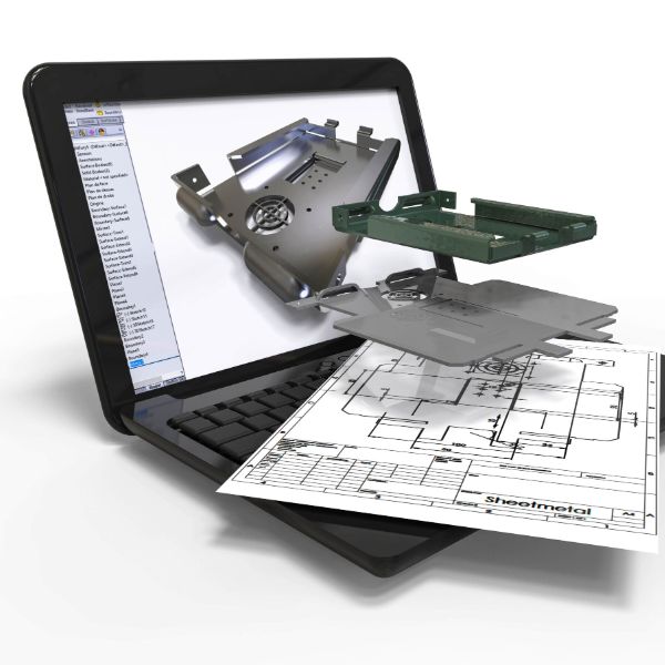
CAD and CAM technology has revolutionised product design and development around the world, and not just for metal fabricators either. All designers, inventors, innovators and machinists alike utilise this technology to:
increase output
create prototypes
establish final goods
create vast production runs
But what is the difference between CAD and CAM? Do they work together? Continue reading to find out more about what both technologies are and the difference between CAD and CAM.
What is CAD?
Before diving into the difference between CAD and CAM, let’s take a quick look into what these both are. CAD stands for Computer Aided Design. Essentially, this involves the use of computers to create 2D technical drawings and 3D models, for the design of physical products. This allows engineers and designers to create and modify model designs quickly and with an extremely high degree of accuracy. In comparison, manually drafting 2D and 3D models can be time consuming and has more opportunity for error.
The other huge benefit provided by CAD design services is the ability to modify a design as and when required, with no extra cost. Experimenting with ideas, real world simulations and different specifications has never been easier, and doesn’t involve having to manually re-build prototypes. Simply modify your design using the computer software, quickly and efficiently, with no risk of it being lost or damaged (as with physical prototypes). You can even share your saved files with your team or subcontractors so everyone is in the loop.
What is CAM?
The main difference between CAD and CAM is that one is design, the other is manufacture. Yes, CAM stands for Computer-Aided Manufacturing. Your CAD 3D model design is turned into a physical product or prototype by the use of software-controlled and automated machine tools. Essentially, CAM converts your CAD into reality. Without CAD, CAM has no purpose as there is no design to create.
CAM software is often used in conjunction with CNC machining. This stands for computer numerical control. It automates the translation of digital designs into detailed manufacturing instructions (often referred to as G-code).
So far we’ve covered the main difference between CAD and CAM – one is design and the other is manufacture. The latter cannot exist or perform without the former, so in essence, they are a unity and feed into each other. When this technology first launche,d it was not so much about the difference between them, but more about the difference in who operates them. Although both processes are computerised and automated to some degree, they both require human input.
A human must input the data and create the design to begin with, at the CAD stage. This was typically a skilled engineer with training in CAD programming software. The CAM side of things was usually handled by a skilled machinist. However, as time moves on and the majority of today’s training is conducted on computers, this difference is not as pronounced and the skillset crossover is more present. The expertise needed to run both CAD and CAM is now comparable. A lot of CAM machines even come with CAD programming already integrated.
This table shows some of the other subtle differences between CAD and CAM.
CAD
CAM
Definition
The use of computers to create, modify, analyse or optimise a design.
The use of computer software to control machinery and automate manufacturing processes.
Purpose
To produce accurate 2D drawings and 3D models of products or components.
To translate CAD designs into instructions for machines to manufacture physical parts.
Key tools required
A computer with CAD software.
A computer with CAM software.
Used by
Designers and engineers
Machinists and manufacturing technicians
Main advantage
Speeds up the design process and improves precision and design flexibility.
Automates production, reduces manual labour and improves manufacturing efficiency and consistency.
Typical outputs
Digital files including technical drawings and 3D models.
Machine instructions (G-code) for CNC machines and other manufacturing equipment.
Typical applications
3D modelling, technical drafting, assembly drawings, simulation and animation
CNC machining, laser cutting, wood turning and metal spinning,
End goal
To define the geometry and structure of a product.
To fabricate a physical version of the product from the digital design.
CAD and CAM: Better together
Although CAD and CAM are distinct tools, they work most effectively when used side by side. CAD software creates detailed digital models, which CAM software then uses to generate the G-code needed for manufacturing. This code turns virtual designs into real-world products.
Ideally, CAD and CAM systems integrate smoothly, with no data loss or compatibility issues. Using software that’s either designed to work together or already fully integrated can streamline production, reduce errors and boost efficiency from initial design through to final output.
Expert 2D and 3D CAD design services with Salamander
CAD design is a crucial early stage in almost every sheet metal project we deliver at Salamander Fabrications. It lays the groundwork for precise manufacturing and well-planned production. This is essential to producing high-quality and reliable components.
We use advanced 3D CAD software (SolidWorks) to bring designs to life, helping to identify potential issues early and ensure each part is fit for purpose. Our team of skilled CAD designers have the expertise to develop cost-effective solutions without compromising on quality, durability or appearance.
For more information or advice on your next project, please do not hesitate to contact us, email sales@salamanderfabs.com, or call 01484 843599.
Corrosion is the natural and gradual deterioration of materials, most commonly metals. This comes as a result of chemical reactions with the environment, for example with oxygen or water. But did you know that there are different types of corrosion? Yes, as one of the enemies of sheet metal fabricators across the land, corrosion has many different forms.
If left untreated, corrosion can:
Weaken structures and components
Reduce the lifespan of equipment
Lead to costly repairs or replacements
Pose safety risks in industrial or structural settings
To prevent this, it’s important to understand the different types of corrosion, so we’ve compiled a handy list of corrosion examples for you in this blog post. Carry on reading for more information on the 7 types of corrosion and some tips on how to avoid them.
Different types of corrosion example
1. Uniform Corrosion
Also known as general corrosion, this is the most common and widespread of corrosion examples. It occurs evenly across a metal surface, typically as a result of direct chemical exposure, such as contact with acids. The initial sign is usually a dulling of the metal, which can progress to a rough, frosted texture if left unchecked.
Although uniform corrosion affects appearance more than structural integrity, it’s still important to address as soon as you can, or as soon as you see it. Protective coatings or corrosion-resistant materials can help prevent it from developing.
2. Pitting Corrosion
This is a highly localised form of corrosion where small pits or cavities form on the surface of the metal. These pits can deepen very quickly, compromising structural integrity while leaving most of the surface seemingly intact. This can make spotting it a little harder, as it can come on subtly and out of sight initially.
Pitting is often caused by defects in coatings, inconsistent metal surfaces or damage to the protective oxide layer. It’s commonly seen in aluminium, stainless steel and nickel alloys. Early detection and proper surface finishing are key to prevention.
3. Galvanic Corrosion
Galvanic corrosion happens when two dissimilar metals come into electrical contact with each other. An electrolyte must also be present, such as saltwater. One metal (the anode) will then corrode quicker than it would alone, while the other (the cathode) is protected. This issue is a common one in marine environments or with chemical processing equipment.
4. Crevice Corrosion
Crevice corrosion develops in confined spaces where stagnant fluids can accumulate, such as between washers, flanges, or metal overlaps. Crevices often have limited oxygen flow, which creates acidic conditions that break down protective oxide layers. This is what leads to corrosion. Improved joint design and careful assembly practices can help minimise the risk of this often hard to detect corrosion type.
5. Fretting Corrosion
This is essentially caused by repeated small movements between two metal surfaces that are under load. This vibration wears away the protective oxide layer, exposing fresh metal that quickly oxidises. The resulting debris gets trapped in the contact area, accelerating both wear and corrosion.
Fretting corrosion examples typically occur in mechanical joints, bearings and bolted assemblies. You can help to prevent this with vibration damping, tighter tolerances and protective powder coatings.
6. Stress Corrosion Cracking (SCC)
This is a result of two factors combining – tensile stress and a corrosive environment. This often occurs at higher temperatures or as a result of expansion and contraction as a result of fluctuating temperatures. It may also be caused by residual stress from the manufacturing process, for example, welding, machining, or cold forming.
With stress corrosion, most of the surface area usually remains intact. But fine cracks do appear in the microstructure, which makes these types of corrosion hard to detect. Choosing appropriate materials for a given environment can help to avoid potential failures.
7. Intergranular Corrosion
This occurs along the grain boundaries of a metal. These boundaries, which separate individual grains within the metal’s crystalline structure, are often more chemically reactive than the grains themselves. This is due to impurities or uneven solidification during alloy formation. This form of corrosion typically happens when a material experiences high temperatures, such as during heat treatment or welding.
In these conditions, carbide precipitation can occur, which reduces the corrosion resistance at the grain boundaries. As a result, the metal becomes more vulnerable to corrosive agents, even if the grain interiors remain intact.
How to prevent corrosion
Here are some general tips you can follow to ensure you avoid the different types of corrosion.
Select corrosion-resistant metals: Materials like aluminium and stainless steel offer durability and are well-suited to various environments.
Apply laser treatments:Laser technology can alter surface structure to enhance corrosion resistance.
Use non-metallic coatings: Grease, plastics, carbon fibre, paint, and oil can act as effective barriers against moisture.
Opt for specialist coatings: Modern powder coatings provide durable, UV-resistant protection without fading, chalking, or the need for multiple layers.
Control moisture: Use drying agents in equipment and storage areas, and regularly check for signs of damp or leaks.
Maintain regularly: Inspect metal surfaces often and repair any damage to protective coatings as soon as possible.
Contact Salamander Fabrications for more information or support
If you would like more information on how to protect your metal projects from the different types of corrosion, please contact us, call us on 01484 843599 or send an email to sales@salamanderfabs.com.
We’re also happy to discuss any of our other services, including:
In the world of sheet metal fabricators, understanding the science behind what are mechanical properties is extremely important. Whether we’re forming, cutting, welding or shaping metal, we must have a deep knowledge of how different materials respond to force and stress. This is essential to ensure durability, performance and safety in the final product.
Selecting the appropriate material involves evaluating its mechanical properties. These are the characteristics that determine how a material reacts when subjected to mechanical loads. These properties help us predict how a component will perform under operational conditions. It also influences everything from cost and efficiency to lifespan and structural integrity.
Our handy guide will discuss:
what are mechanical properties
the key mechanical properties of some common metals and alloys
explain their relevance to a wide range of fabrication and engineering applications
Keep reading for more information!
What are mechanical properties?
Mechanical properties describe how a material responds when external forces are applied to it. This includes properties like tensile strength, elasticity, ductility and toughness (more of that to follow). Unlike physical properties (such as density or melting point) mechanical properties are about how a material performs under load, strain or deformation. Understanding these behaviours is fundamental when designing components expected to endure various stresses. This could be a support bracket within a structure, a sheet formed panel in an automotive application, or a precision cut component in electronics.
On the other hand, physical properties are not influenced by applied forces. This includes density, melting point, thermal conductivity and electrical resistivity. To put it simply, physical properties determine how a material interacts with its environment, while mechanical properties tell us how it will perform when under operational stress.
Key mechanical properties of metals
Here is a detailed overview of the primary mechanical properties relevant to sheet metal fabrication services and metalworking in general.
Hardness
Hardness is the resistance of a material to deformation, scratching or wear. It is also related to how well one metal can cut into another. Hardness is usually tested using Brinell, Rockwell or Vickers methods.
Toughness
Toughness is the ability of a material to absorb energy and resist fracture. It combines strength and ductility and is vital for parts exposed to impact or shock loads.
Elasticity
Highly elastic materials return to their original shape once the force is removed. Metals like steel are highly elastic as they return to their original dimensions after small deformations.
Plasticity
This is the ability of a material to undergo permanent deformation without breaking. It is a vital property for metal forming processes such as bending, forging or rolling.
Malleability
This property enables a material to be deformed under compressive forces into thin sheets. Aluminium and copper are both highly malleable materials.
Stiffness
Stiffness refers to a material’s resistance to elastic deformation under load. A stiffer material bends less under the same force. This is typically measured using the modulus of elasticity (Young’s Modulus).
Ductility
Ductility refers to a material’s capacity to be stretched into a wire or thin form without breaking. It is usually measured by the percentage elongation or reduction in area before fracture. Common ductile metals include copper, aluminium and mild steel.
Resilience
This is a measure of a material’s capacity to absorb energy within its elastic range. Resilient metals are often used for springs and components that experience frequent shock or vibration.
Strength
This is the ability of a material to withstand applied force without failure. This includes tensile strength, compressive strength, and shear strength.
Fatigue
Fatigue is the gradual weakening of a material due to repeated loading and unloading cycles, often leading to failure at stress levels well below the material’s tensile strength. It is a major consideration in rotating machinery and structural components.
Brittleness
Brittle materials fracture without significant deformation. Unlike ductile metals, they do not stretch or compress much before breaking. Cast iron is a classic example.
Machinability
Machinability refers to how easily a metal can be cut, shaped or finished. Metals like brass and aluminium are considered highly machinable, making them suitable for precision engineering.
Creep
Creep occurs when a material slowly deforms under constant stress at elevated temperatures. It is a crucial consideration in high temperature applications such as engines, turbines and boilers.
Applying mechanical properties in sheet metal fabrication
The relevance of these properties becomes clearer when choosing materials for specific fabrication tasks. By carefully selecting a material based on its mechanical properties, sheet metal fabricators can ensure performance, longevity and safety in the final product.
Materials exhibit a wide range of other properties in addition to mechanical properties. We’ve listed some of them below.
Thermal properties
Thermal performance is critical in applications that involve high or fluctuating temperatures. For example, in industries such as automotive, aerospace and construction.
Key thermal properties include:
Thermal conductivity: a measure of how effectively heat flows through the material.
Specific heat capacity: the amount of energy needed to raise the material’s temperature.
Boiling and melting points: essential for selecting materials that must endure extreme heat or undergo phase changes
Electrical properties
Electrical properties tell us how materials behave when exposed to electric fields. This includes whether a material conducts or insulates electricity and its ability to resist electrical breakdown. Another consideration is piezoelectricity, which is the capacity of certain materials to produce electric charge under mechanical stress. These properties are vital in electronics, sensors, circuit boards and control systems.
Optical properties
These define how a material interacts with light. It is especially relevant in display technologies, solar panels and lighting systems. Measurements include the amount of light that passes through the material, how light is bent or reflected, absorbance and colour.
Magnetic properties
Magnetic behaviour varies greatly between different metals and involves hysteresis and permeability, which relate to how materials retain and transmit magnetic energy. These are essential in the design of electric motors, transformers and magnetic shielding.
Chemical properties
Chemical reactivity and stability are vital for material selection in harsh or corrosive environments. Key attributes include corrosion resistance and reactivity, as well as pH behaviour and surface energy. This is really important for bonding, plating and coating applications.
Acoustic properties
In applications that require sound management, materials are assessed for sound absorption, reflection and transmission. The speed of sound through the material is also influenced by density and elasticity.
Manufacturing properties
This includes machinability, formability, castability and weldability. This all helps to determine how easily or efficiently a material can be shaped or joined. This often involves fatigue limits and elastic modulus, which affect how materials behave during and after fabrication.
Contact Salamander Fabrications today for your sheet metal fabrication needs!
Whether you need components for the transportation, energy, construction or manufacturing sectors, the right knowledge of material properties can mean the difference between a reliable part and a costly failure.
With over 50 years of industry expertise, Salamander Fabrications is a trusted name in UK based sheet metal solutions. From laser cutting and CNC folding to powder coating and assembly, we bring precision and quality to every project.
Our team is on hand to help you select the right material for your application, one that matches your needs in both mechanical performance and cost efficiency. Get in touch today for tailored advice, a quote, or to learn more about how we can support your project.
We use cookies to ensure that we give you the best experience on our website. If you continue to use this site we will assume that you are happy with it.